At Coltraco, we pride ourselves on our UK-made instruments’ quality, reliability, and accuracy, including ultrasonic flow meters. Our ultrasonic flow meter technology has been tested and calibrated at an ISO 17025 laboratory, meeting an accuracy of +/- 0.5% of the true flow rate.
Using non-invasive technology, our transit time flow meters have significant advantages over inline flow meters by reducing installation cost, risk, and downtime for your flow rate measurements.


We are proud winners of the Queen’s Award for Enterprise in International Trade, in both 2019 and 2022.
An ultrasonic flow meter is a non-invasive flow-measuring device that uses sound waves to determine the flow rate of liquids. Offering high accuracy, low maintenance requirements, and versatility, these flow meters can be used for various applications, including industrial processes, water treatment, and energy management. Additionally, ultrasonic flow meters operate without moving parts, resulting in minimal pressure loss and reduced maintenance.
Ultrasonic flow meters work by sending sound waves through the liquid and measuring how long it takes to pass through. Sound waves are sent in the direction of the flow, and the flow rate is generated based on the transit time between two points.
There are two main types of ultrasonic flow meters – transit time flow meters and Doppler flow meters. Coltraco Ultrasonics offer ultrasonic transit time flowmeters that are high in accuracy and versatility using clamp-on sensors.
The operation of ultrasonic flow meters relies on ultrasonic flow measurement methods, such as the transit time method and the Doppler method, to accurately determine flow characteristics.
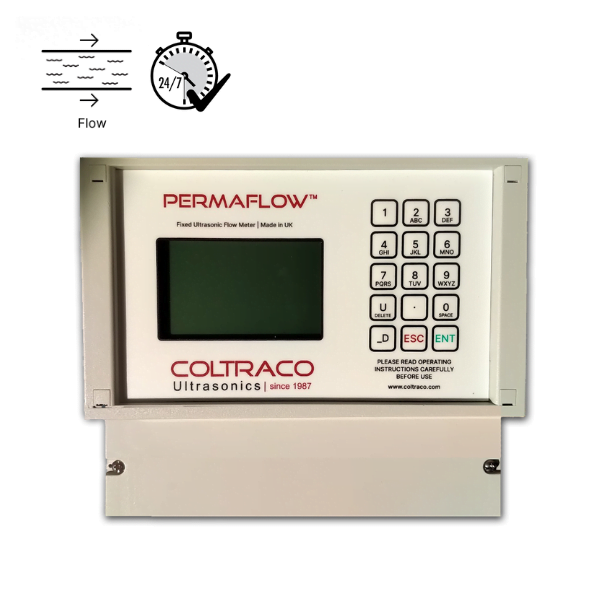
Transit-time ultrasonic flow meters measure the difference in transit time between sound waves travelling with and against the flow. In this type of meter, two transducers are installed on opposite sides of the pipe, one sends a sound wave through the fluid in the direction of the flow, and the other receives it. The transit time is then calculated by comparing the time the wave travels from the first transducer to the second transducer with and against the flow. These are the Portasonic® and Permaflow® product range.
Doppler ultrasonic flow meters, on the other hand, measure the frequency shift of sound waves reflected off of moving particles in the fluid or gas bubbles. In this type of meter, a single transducer sends a sound wave into the fluid, and the frequency shift of the wave is measured as it is reflected off of moving particles in the fluid.
The Doppler method is particularly suitable for measuring flow in fluids containing suspended solids or gases, as these sound-reflecting particles or bubbles are essential for accurate detection. This method can also be used to measure flow in vessels, such as industrial pipes or even blood vessels in medical applications.
The flow rate can then be calculated based on the frequency shift of the reflected wave. Coltraco Ultrasonics currently do not have any Doppler Flow Meters in our range.
Ultrasonic flow meters can be used for various commercial applications, including liquid measurement flow in full pipes, the measurement of clean liquids, including water, wastewater, oils, solvents, acids, and other conductive liquids, and the control of HVAC systems. The ultrasonic flow meter is ideal for applications where disrupting the flow is not an option as the technology is non-invasive and introduces zero downtime to the system.
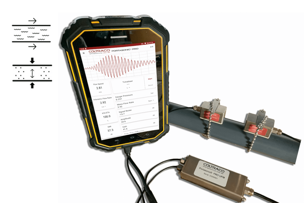
These ultrasonic meters offer non-invasive flow measurements from outside the pipe wall. Using ultrasonic transducers that are clamped to the external wall of the pipe, the devices use ultrasonic pulses to determine flow rate and transit time.
Ultrasonic flow meters are compatible with a wide range of pipe sizes and can be used on lined pipes, such as concrete-lined or plastic-lined pipes, though lining may impact measurement accuracy. The presence of air bubbles or entrained air in the liquid can also affect the accuracy of ultrasonic flow measurements.
The Portasonic® and Permaflow® range of ultrasonic flow meter works on the transit-time principle. The principle of flow measurement using ultrasonic clamp-on transit time measurement is simple and can be illustrated in the figure below.
Transit time and Doppler technologies are two main ultrasonic flow measurement methods; transit time is ideal for clean liquids, while Doppler technologies are better suited for applications involving fluids with suspended particles or bubbles.
Two ultrasonic sensors are clamped to the outside of the pipe at a predetermined distance apart. The ultrasonic signal travels between the transmitters through the pipe wall and the fluid within the pipe. If the fluid is flowing, then it takes slightly longer for the ultrasound to travel against the flow (upstream time T_up) than with the flow (downstream time T_down).
While clamp-on ultrasonic flow meters are non-intrusive and easy to install, in-line ultrasonic flow meters are installed directly within the pipeline as intrusive, wetted devices. In-line solutions are often chosen for applications requiring custody transfer or highly accurate and reliable flow measurement, offering precise diagnostics compared to clamp-on types.
In a typical installation, the individual times measured upstream and downstream are just a few hundred microseconds, the difference between them is typically measured in tens of nanoseconds.
It is important to consider the power requirements or power supply specifications for the ultrasonic flow meter’s control unit and components to ensure proper operation.
This very small time difference (T_up – T_down) is measured by the flowmeter and is directly proportional to the fluid’s flow velocity (V).
Ultrasonic flow meters use a single ultrasonic transducer that emits high-frequency sound waves into the fluid. The sound waves reflect off the particles or bubbles in the fluid and create a frequency shift known as the Doppler shift. The change in frequency is proportional to the fluid velocity. The flow velocity and volume can be calculated by measuring the Doppler shift.
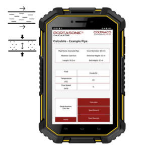
Volumetric Flow Rate: Knowing the pipe’s internal cross-sectional area, the ultrasonic flow meter can calculate the volume flow rate in many common engineering units such as litres per hour (l/h), gallons per minute (GPM) etc. This gives a measurement unit similar to that given by a vortex flow meter, variable area flow meter, differential pressure flow meter, or another inline flow meter.
Mass Flow Rate: Incorporating the density of the fluid allows the ultrasonic meters to calculate the mass flow rate. This gives a similar measurement unit to that given by mass flow meters or Coriolis meters.
Heat or Energy Flow Rate: A knowledge of inlet and outlet fluid temperature and the specific heat capacity of the fluid allows the flow meter to calculate the heat flow rate. This is suitable for energy efficiency calculations for heating and chilling applications.
Totalised Flow: Both the Portasonic® PLUS and Permaflow® come with a flow totaliser function. The flow totaliser totalises (adds up) the volume of fluid that has flowed through the pipe. The totaliser function allows these rates (Volumetric Flow Rate, Mass Flow Rate, Heat or Energy Flow Rate) to be totalled and positive, negative and net values can be displayed.
Our flow measurement devices provide accuracy and reliability, as proven at an ISO 17025-certified laboratory. We’re committed to providing the highest quality instruments to the UK market while remaining competitive on price. These ultrasonic meters are built with a special composite material to optimise ultrasound transmission, and all units come with a built-in oscilloscope for signal diagnostics that assists you in performing reliable measurements.
Our transit-time meters far surpass mechanical flow meters, with an accurate flow sensor that can calculate volume flow easily. Each ultrasonic flow meter from Coltraco is designed to cater to a wide range of pipe sizes. They are virtually maintenance free and once they’re installed, these ultrasonic flowmeters get straight to work.
In addition, Coltraco offers professional services, including technical support and system monitoring, to ensure optimal performance and accuracy of ultrasonic flow meters.